E-Scooter Battery Build
Replacement 13S6P Li-Ion AliExpress Kit for my Xiaomi Mi 2
Post published on July 04, 2026.Background
For some years now I own a Xiaomi Mi 2 scooter. Of course I flashed it with SHFW using the ST-Link method, which then allows using the normal SHFW Android app to do all updating and configuring.
This worked perfectly fine for about 2500km. Then the internal battery was noticeably degraded and I could no longer reach home from work in winter.
So I got one of the last Rita adapters before the product was discontinued, which allows connecting an external battery with differing voltage for range extension.
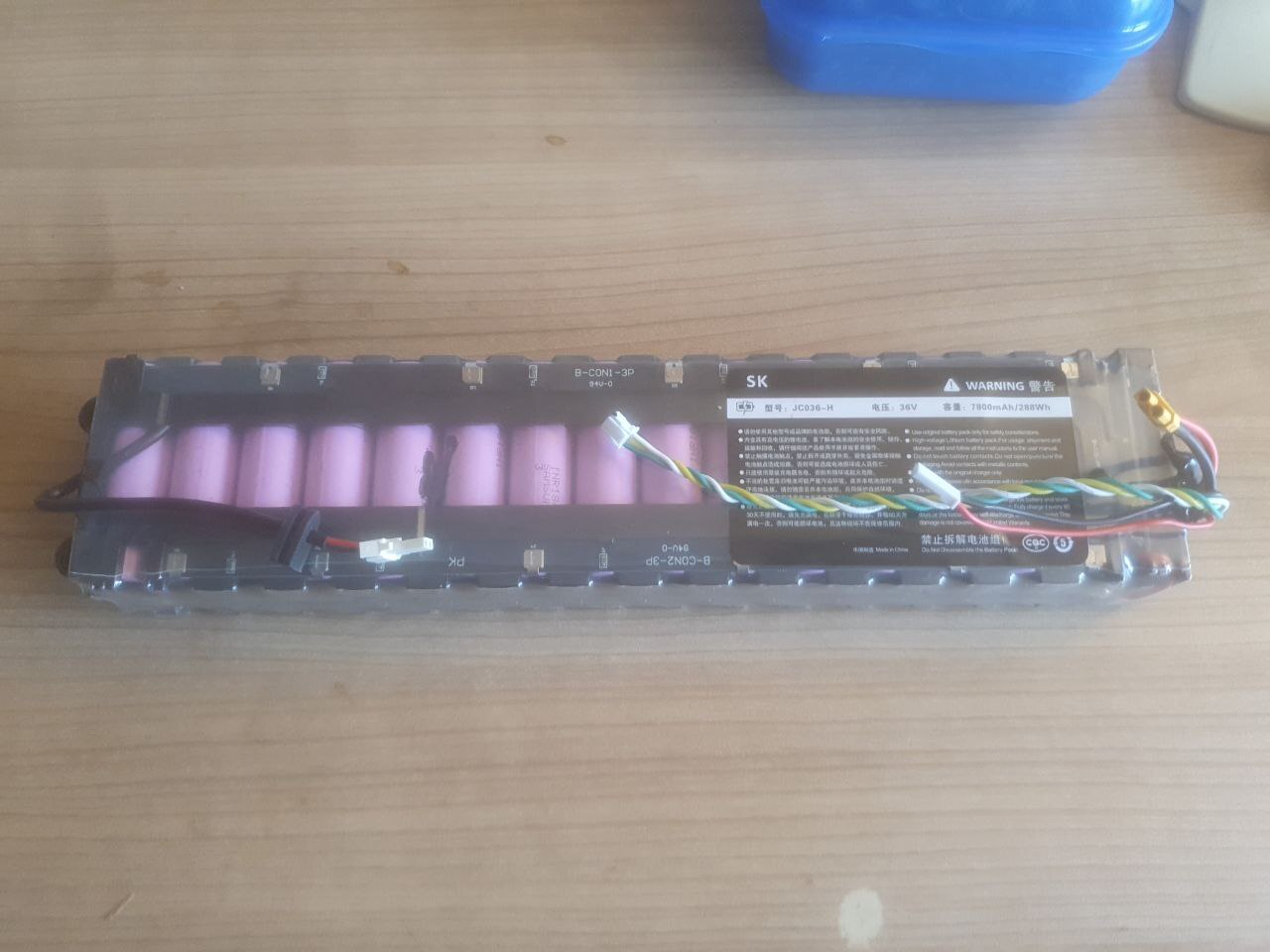
A colleague of mine bought a 13S6P battery on AliExpress which he didn't end up using, so I got that from him. Unfortunately it was total crap, and died much much quicker. After only a handful of trips, I could again not reach work anymore.
Still not having learned my lesson, I got a "new" internal Xiaomi scooter battery from AliExpress as well, which was just as bad and died in just a couple of trips.
So finally I decided to build my own.
Build
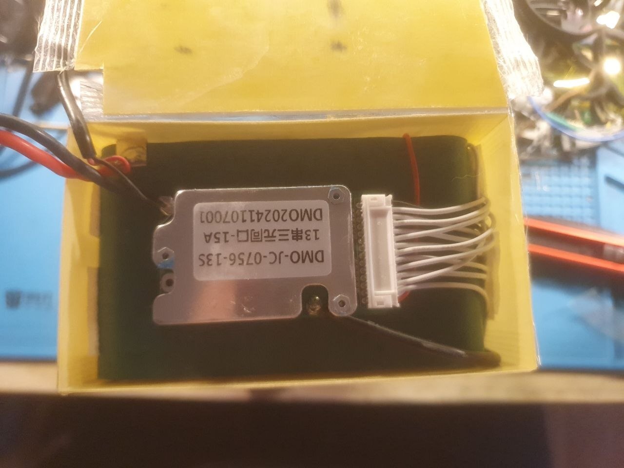
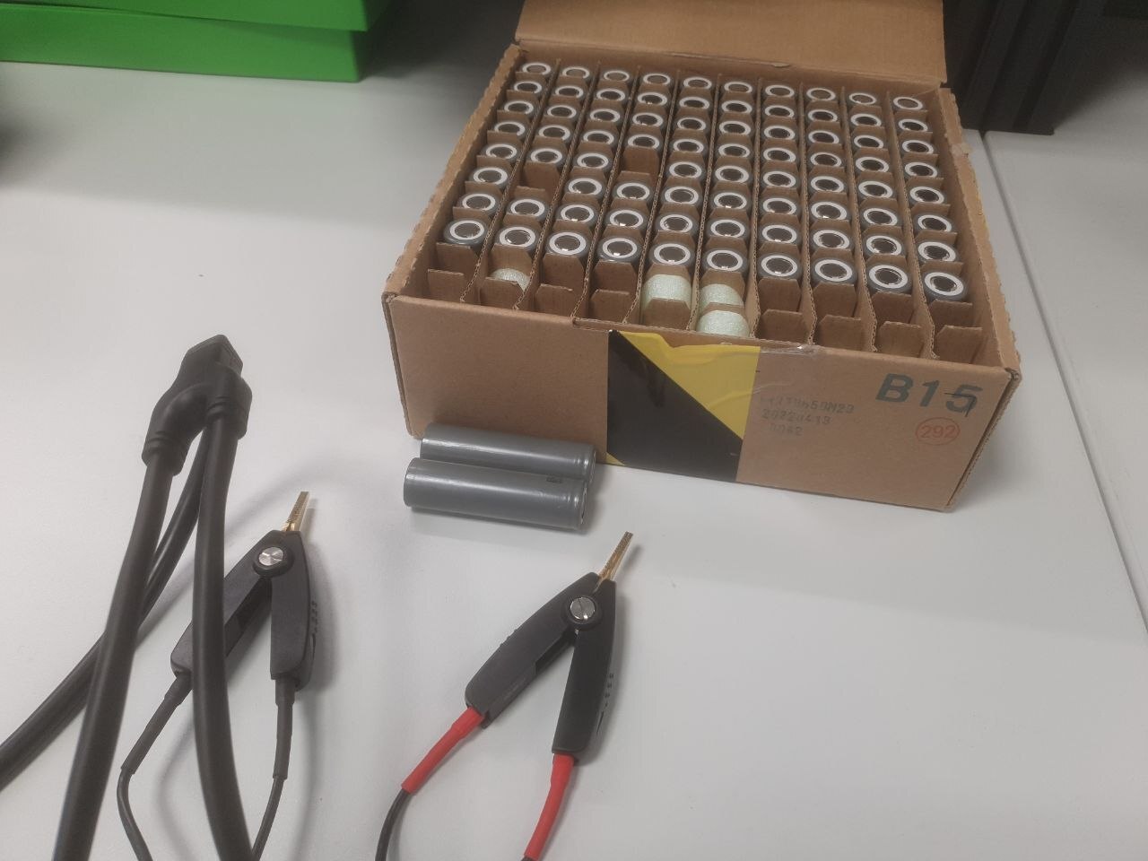
In my scooter config I've set a maximum current of 28A, so I decided to get a DIY battery kit from AliExpress with nominal support for 30A, in a 13S6P configuration. 30A divided by 6 cells in parallel gives a discharge current of 5A per cell.
Looking around online I decided to go with nkon.nl as they are a well-known large supplier of cells in Europe.
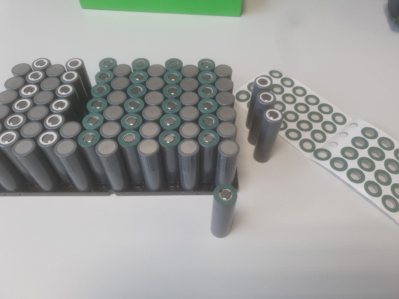
There I found the INR18650-M29 cells from LG, which support a surge discharge current of 10A and continuous discharge of 6A, according to their datasheet.
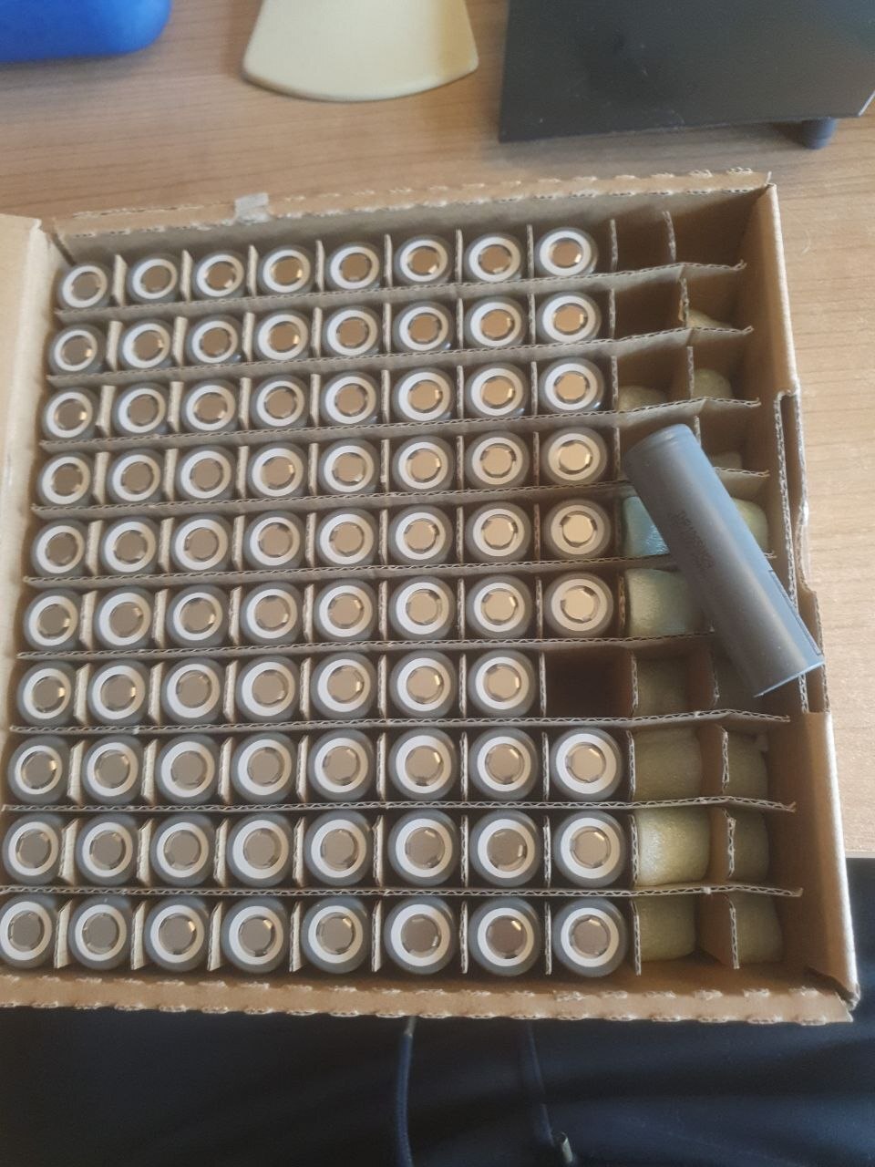
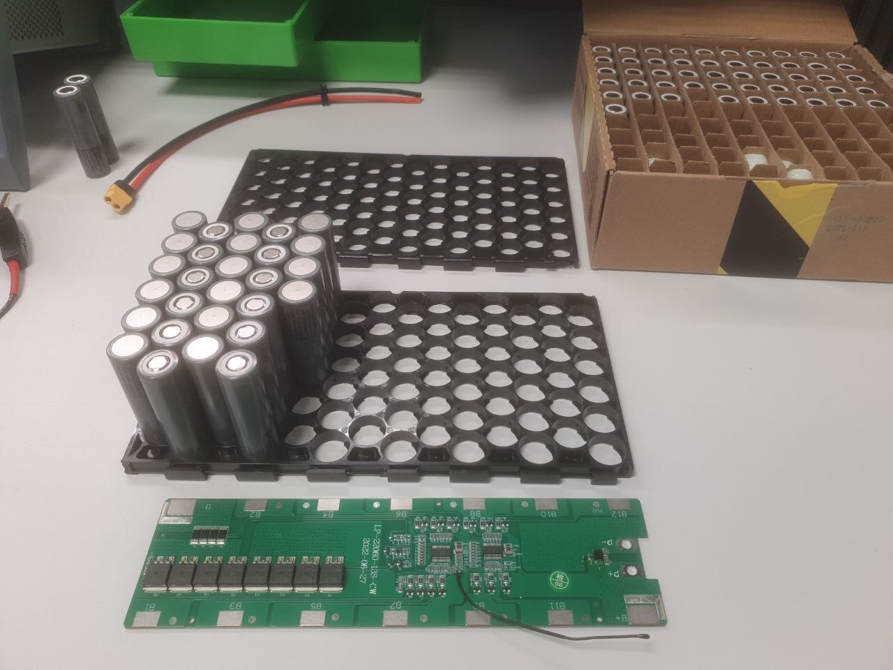
As mentioned above, I checked the internal cell resistance, but you don't necessarily have to do that, as long as you use cells from one batch.
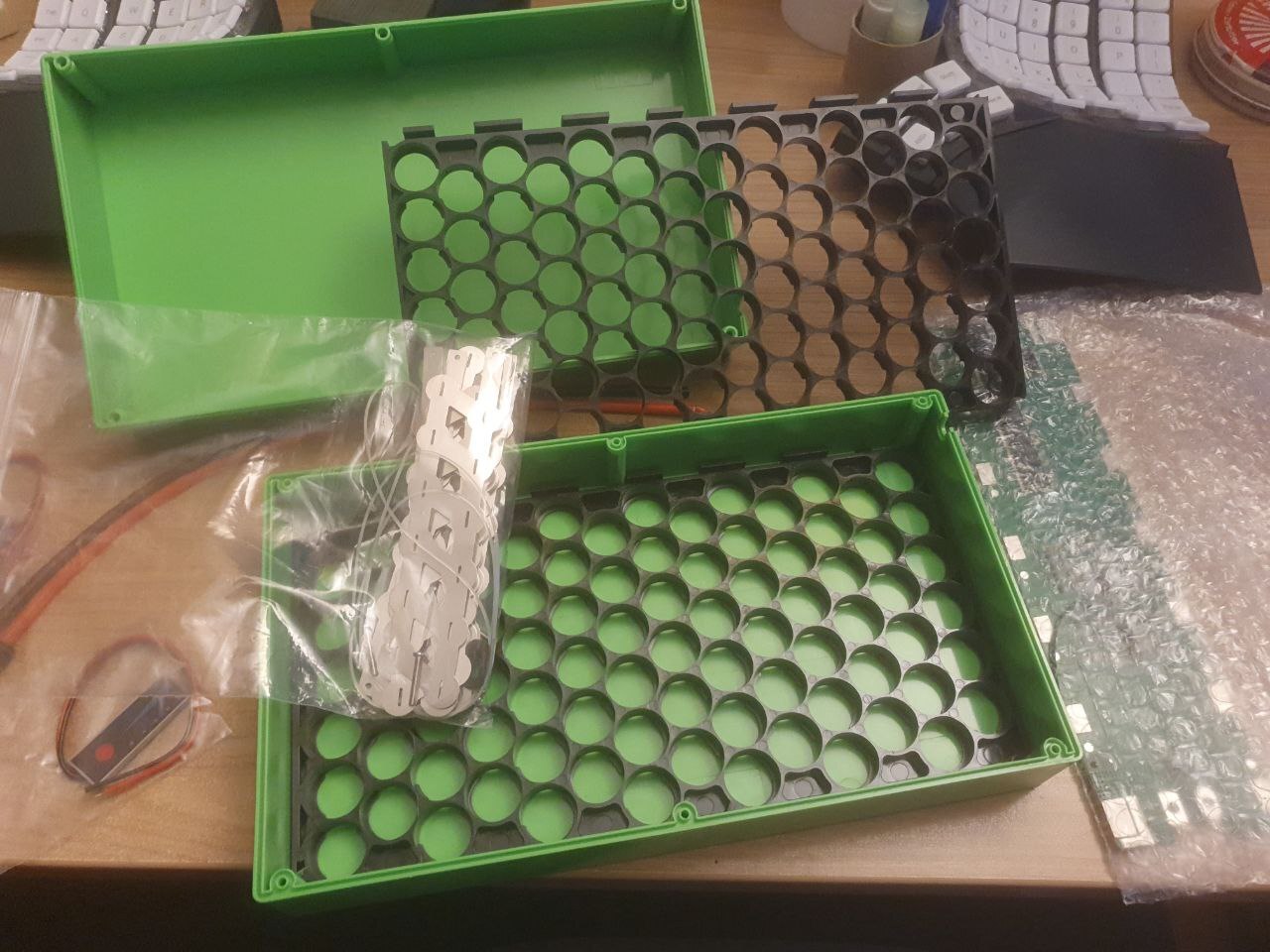
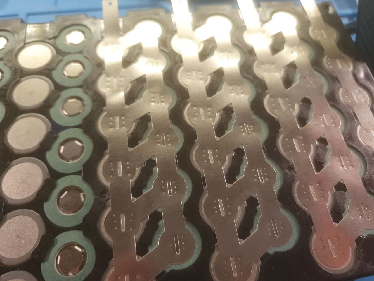
Now just stick them all into the carrier and attach the paper rings to the positive poles, to protect from shorts with the negative pole around the perimeter of each cell.
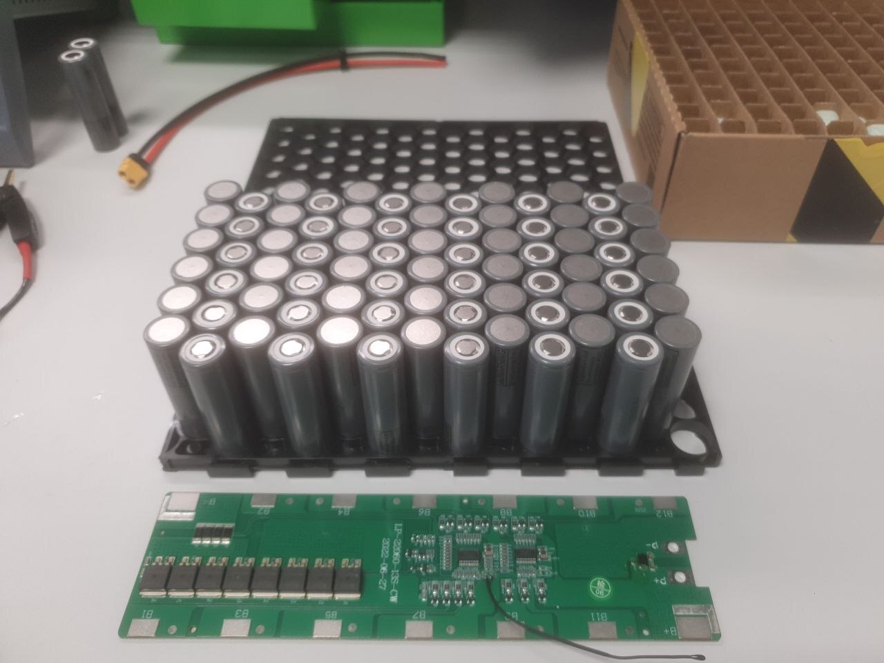
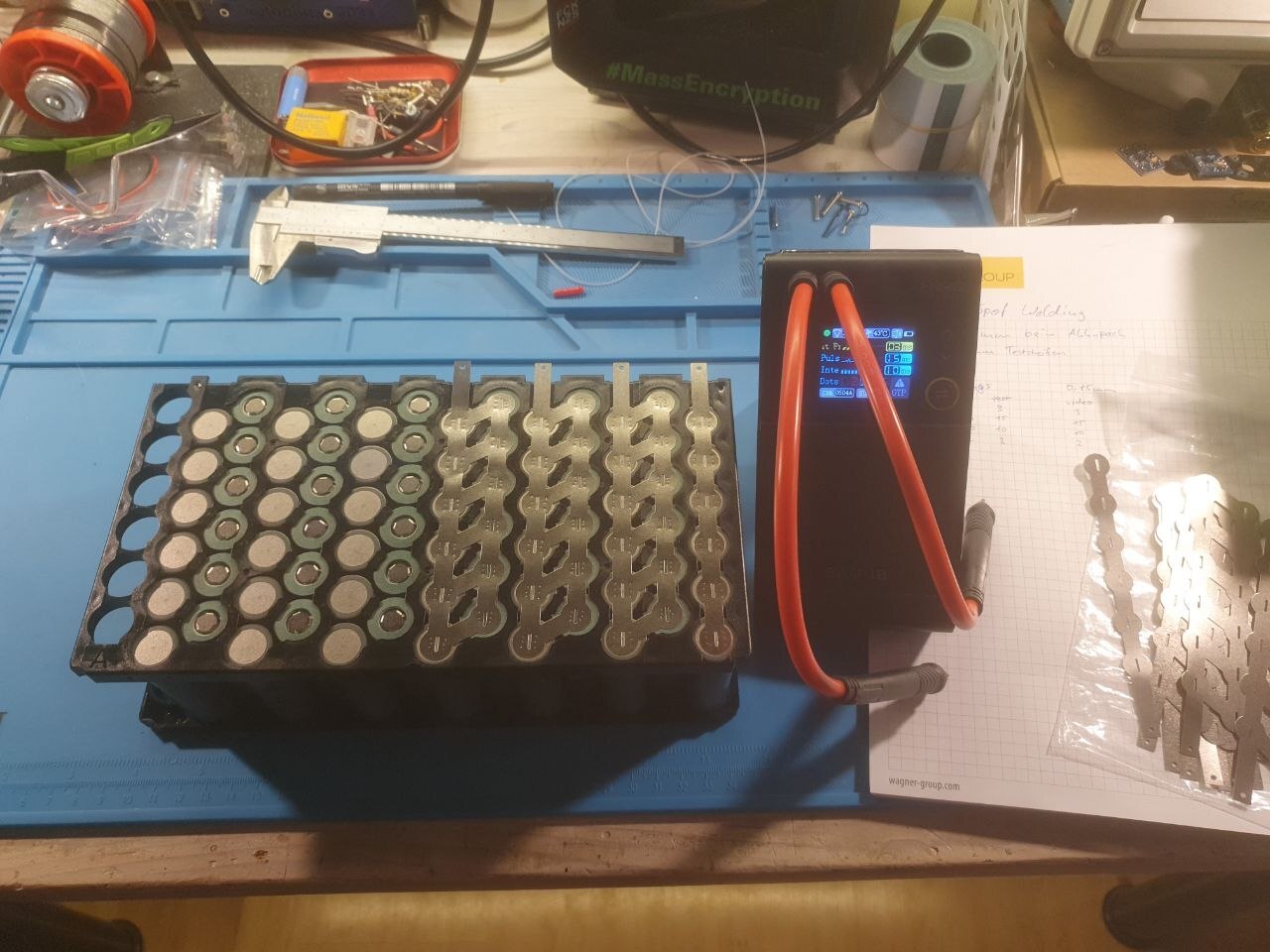
Then do the spot welding. I recommend doing some testing first on an unused cell, which is how I arrived at the settings mentioned above. I ended up with four welds per cell pole.
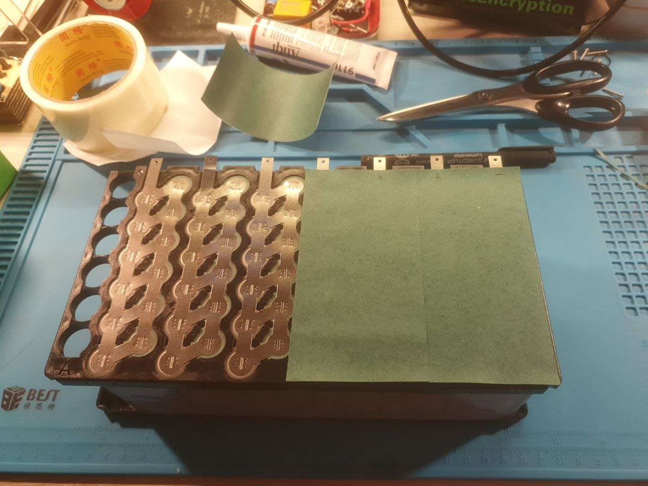
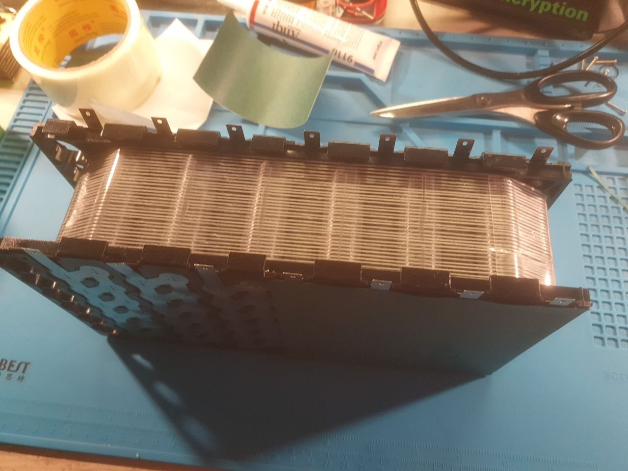
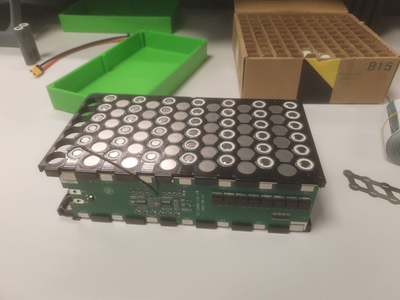
The whole thing was covered with more insulating paper, and some battery fibre tape to hold the cells firmly in place.
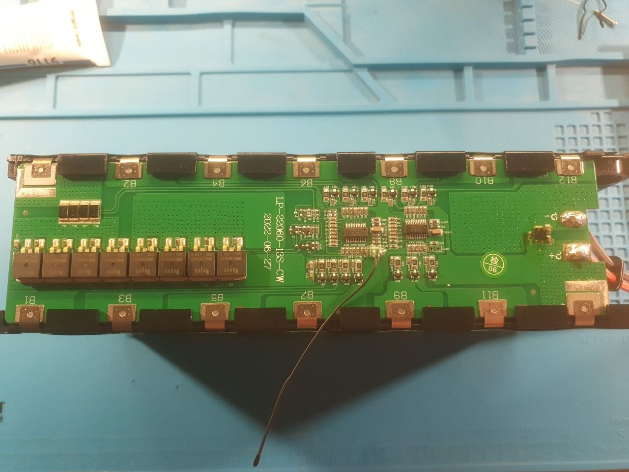
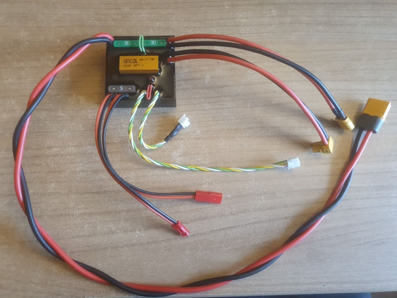
The BMS can also be welded, just the (dis)charge leads need to be soldered. Use thick wires for that, rated for the current. Therefore you will also need a beefy soldering iron to get them soldered to the PCB without unnecessary heating of other components.
Tools Used
Fortunately I have some access to tools at work.
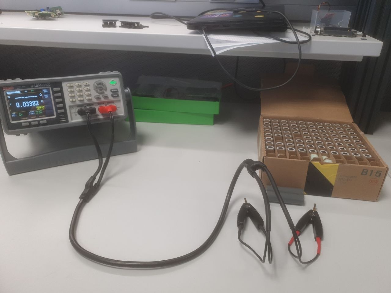
So I used their RS Pro RSBM-3300 Battery Tester to check the charge state and internal resistance of each cell. This turned out to be unnecessary though, as all cells came from the same batch and had matching voltages and resistances.
For spot welding I used the FNIRSI SWM-10. The settings I was happy with are:
- Preheat:
3ms - Pulse:
15ms - Interval:
10ms - Dots:
3
Although all around I don't like this spot welder very much.
It's made with a single very beefy lithium cell inside, that seems to just be shorted for welding, which is fine.
But the charging and safety monitoring of this cell seems problematic.
It was deep-discharged by itself after some time on the shelf, and when left to charge it stopped the charge at a cell voltage of 4.3V, which is overcharging the cell.
So be careful with that, if you own the device yourself.
Some people online suggest only using it with slow USB chargers with 500mA or so.
It also took around three or four recharges of the spot-welder battery to finish this project.
Bill of Materials
These are the consumables I bought, with the price I paid at the time.
With these 2.85Ah cells, arranged as 6 in parallel, the resulting capacity of the pack is 17Ah.
And the 13 strings of these in series give a nominal voltage of 48V.

